AP 242 Edition 2 has enhanced functionalities for CAD 3D PMI (Product and Manufacturing Information) interoperability
The objective of this page is to provide an overview of the enhanced functionalities of AP 242 edition 2 in development for 3D Product and manufacturing information (PMI) interoperability. It is summed up according to the following paragraphs:
- Location of the PMI in lifecycle
- Overview and illustration of capabilities
- Examples of associated use cases
- Dependencies / related standards
- Status of development
Location of the PMI in lifecycle
The information is created in the detail design activities by the design office.
Overview and illustration of capabilities
Edition 2 capabilities and target use cases include Edition 1 capabilities and supported use cases. Below are the capabilities brought by the 2nd Edition:
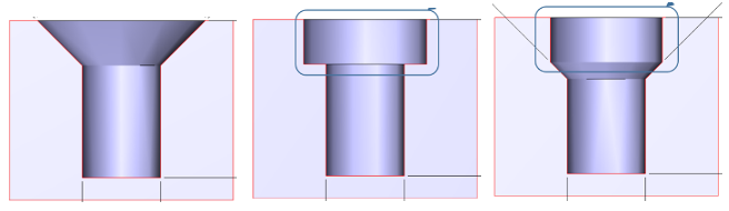
- Extension of hole features for new use cases in part and assembly:
- Single diameter hole with placement data but no geometric model,
- Counterbore with placement data but no explicit geometric model,
- Counterdrill with optional explicit geometric model,
- Counterdrill with placement data but no geometric model,
- Countersink with optional explicit geometric model,
- Countersink with placement data but no geometric model,
- Spotface with optional explicit geometric model,
- Spotface with placement data but no geometric model.
- Extension based on ISO 1101:
- Intersection plane, orientation plane, Collection plane
- United feature modifier UF
- Specified tolerance zone offset UZ
- Modifiers for associated toleranced feature specification element Ⓒ, Ⓖ, Ⓝ, Ⓣ, Ⓧ
- Modifiers for reference feature association specification elements C, CE, CI, G, GE, GI, N, X, Modifiers for parameter specification elements T, P, V, Q,
- Geometric tolerances with a Restrictive specifications where the unit sizes is in degrees
- “All over” in ISO TC213, Globally-Applicable Specifications, unless otherwise specified
- Extension of the saved view capability at assembly level and to a definition of a default view
- Annotation placeholder occurrence
- General notes / Flag notes
- Topological identification for design to design and design to downstream uses (permanent ids):
The capability to support design iteration between two CAD systems where there are topological differences in two CAD systems.
E.g., where one system uses one topological representation item and the other system uses multiple topological representation items for the same occurrence.
E.g., support design iteration of a cylinder between two CAD systems where one system specifies the cylinder with two faces and the other specifies it with one face.
- Datum systems enhancement
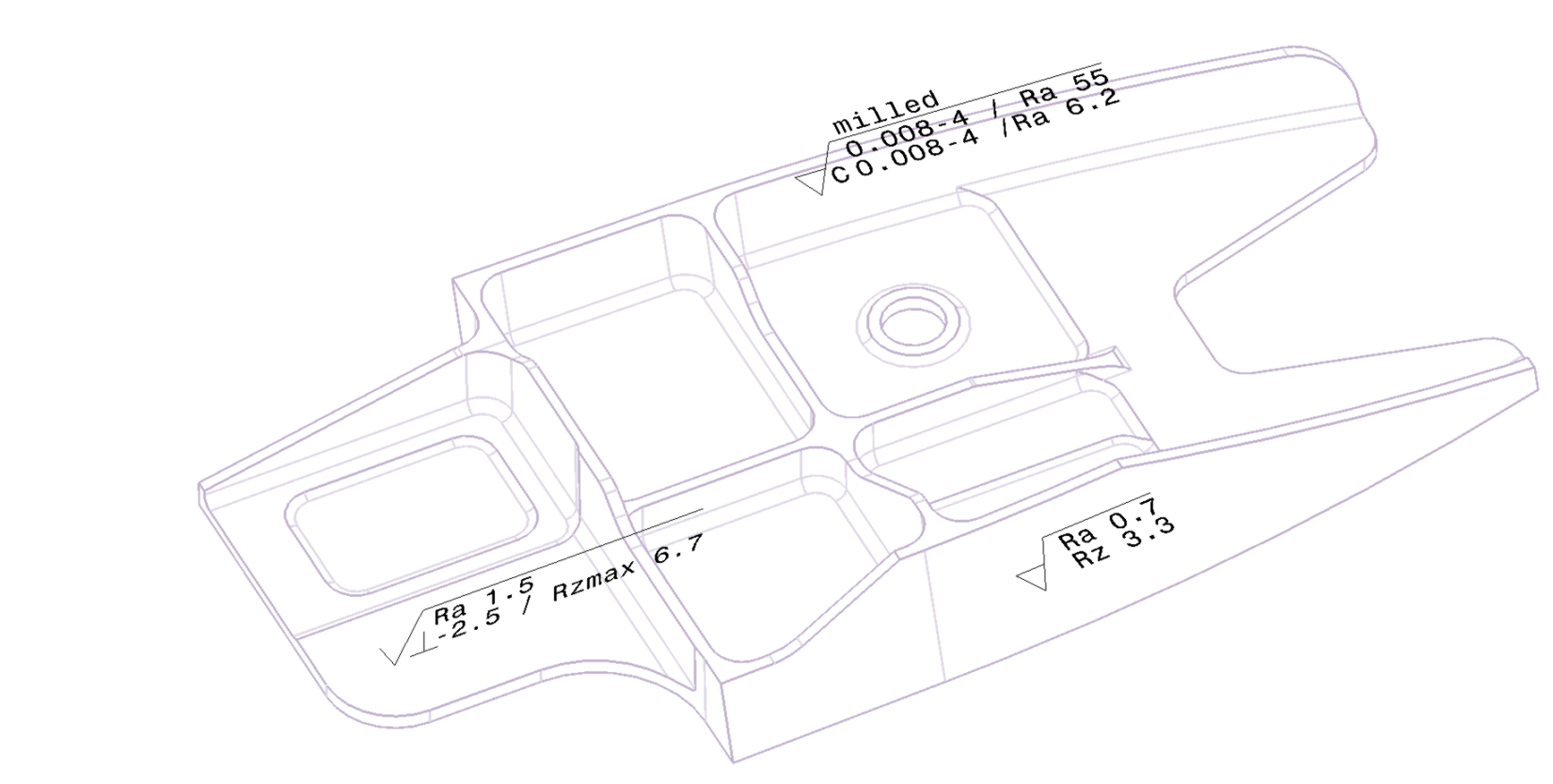
- Surface texture : Semantic representation of the surface texture PMI based on
- ISO 1302: 2002 Geometrical Product Specifications (GPS) -- Indication of surface texture in technical product documentation
- ASME Y14.36M-1996 Surface Texture Symbols
Example of associated use cases
- Interoperability between different systems
| |
| CAD-CAE | Design PMI to Engineering Analysis
| |
CAD-CAD
|
CAD 3D geometry with PMI exchange with the supply chain
| | CAD-CAM | CAD 3D with PMI "semantic" exchange for down stream reuse |
|
- Long Term Archiving and Retrieval (LTA&R):
- LTA&R of CAD 3D PMI "graphic" for certification
- LTA&R of CAD 3D with PMI "semantic" design for manufacturing and repairs
Dependencies / related standards
- ISO GPS standards
- ASME standards
Current development
- GUID: global unique identifiers
- ISO GPS additional extension (ISO 1101, ISO 5459, ISO 16792) and ASME Y14.5-2018
- Screw thread : Semantic representation of the Aerospace screw thread based on:
- SAE AS8879D Screw Threads - UNJ Profile, Inch
- ISO 3161:1999 Aerospace -- UNJ threads -- General requirements and limit dimensions
- Weld : Semantic representation of the weld based on
- AWS A.24 edition 2012 Standard Symbols for Welding, Brazing, and Nondestructive Examination
- ISO 2553:2019 Welding and allied processes -- Symbolic representation on drawings -- Welded joints
(1) butt joint (2) simple V joint (3) lap joint (4) T-Joint (5) corner joint
update 2020-09-11