AP 242 Edition 2 capabilities for Additive Manufacturing interoperability
This is an overview of the enhanced capabilities of AP242 edition 2 in development for 3D CAD interoperability of additive manufacturing (AM) information.
- Overview and illustration of capabilities
- Dependencies and related standards
- Status of development Prototype
- Use cases
- Future development
Overview and illustration of capabilities
More functions traditionally found in additive manufacturing specific software (setting a build orientations, part placement in the build environment, and design of support structures) are migrating to CAD software. These functions are still a part of the 3D printing process, but eventually will become a CAD design function. The major CAD software companies are developing those capabilities or integrating existing AM software into their software. There is a need to capture the information associated with those functions in a STEP file for interoperability and long-term archiving and retrieval.
The following AM capabilities are in the scope of STEP AP242 edition 2
- Build orientation: Direction vector associated with part
- Build plate size: XY dimensions of plate
- Build volume (add height to build plate)
- Build plate placement
Dependencies and related standards
- AP242 edition 2 3D geometry (Curved triangle based on cubic Bezier triangle)
- STEP AP238 / STEP NC
- CAxMan (European project)
- ASTM F42 for the ISO/ASTM 52921 definition of AM coordinate systems for build plates and parts
- ASME Y14.46 Product Definition for Additive Manufacturing
- LOng Term Archiving and Retrieval – EN/NAS 9300 LOTAR
Status of development
This part of ISO 10303 specifies an application module for the definition of additive manufacturing part and build information. The module "Additive manufacturing part and build information" is included in AP242 edition 2 “Draft International Standard”.
For example, additive manufacturing processes require that a build orientation be specified so that the resulting part has the required physical properties, surface finish, geometric accuracy, and definition of support geometry. Placement of the part within the additive manufacturing system build volume might also be specified. This requires the definition of build plate and volume geometry.
The following are within the scope of the module "Additive manufacturing part and build information":
- definition of the part build orientation and placement on the build plate
- definition of the required minimum manufacturing build volume
- identification of the geometry for the support structure
Other STEP capabilities not specific to additive manufacturing:
The module "Additive manufacturing part and build information" is defined in addition to the other STEP capabilities. These new entities can be used with every kind of STEP geometric shape representation such as advanced B Rep, tessellated shape representation, or the new curved triangle based on cubic Bezier triangle. It is also possible to have the graphic presentation or semantic representation of PMI annotation in the same STEP file.
Tessellated geometry was introduced in the STEP AP242 edition 1. The STEP tessellated model is compatible with all functionalities referencing 3D PMI and user-defined attributes. Tessellated geometry can be linked to exact boundary representation geometry when present. Thanks to a simple data model (see the CAx-IF recommendation), it allows an easy implementation in a compact files (see also CAx-IF recommendation).
Prototype
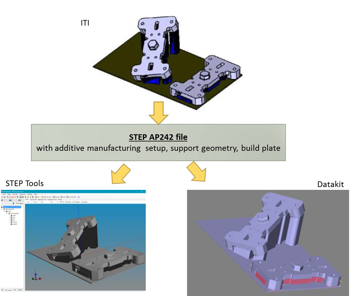
Prototype implementations were developed to validate the usage of the MIM entities introduced by the module "Additive manufacturing part and build information". The entities usage was described in a recommendation document.
Several STEP files were created by ITI and NIST and imported by STEP Tools and Datakit. The tests were done based on the NIST PMI test case CTC 1. For the part definition, an exact geometric representation has been used. For the support geometry, the tessellated geometry has been generated. The support geometry was generated in Materialise Magics software and export to STL and converted to STEP tessellated geometry.
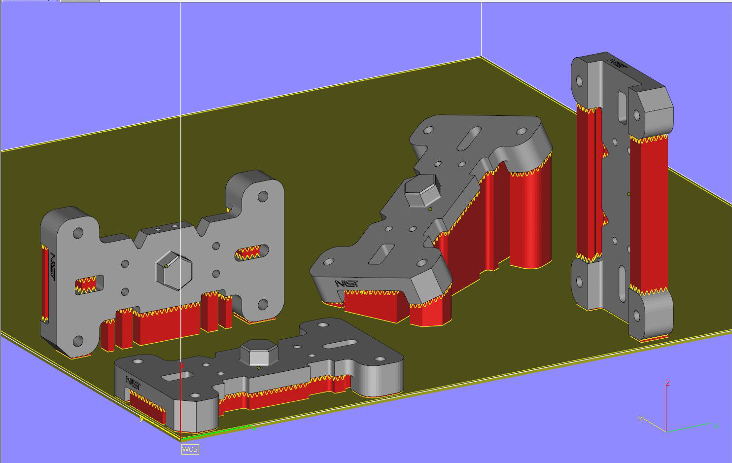
Test 1: a setup of a part with its support structure. The setup includes an explicit geometric representation of the build plate.
Test 2: a setup of two part with their support structures. Each two part has different build orientations. The setup includes the representation of the build plate.
Test 3: several built directions without representation of the build plate.
The following picture illustrates the Result of test 2:
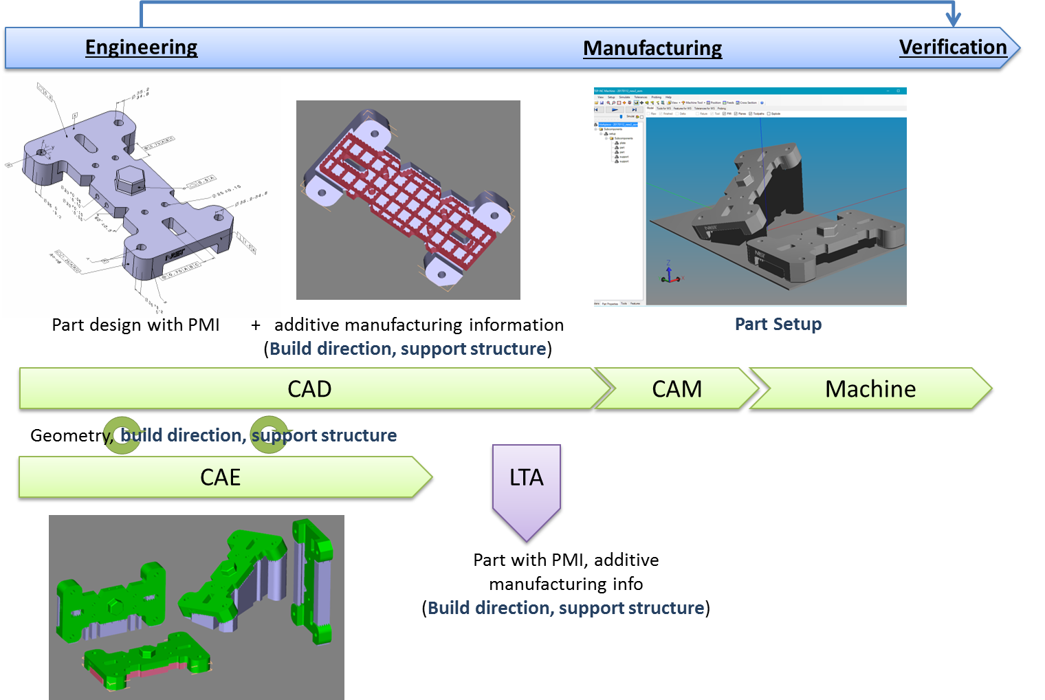
Example of associated use cases:
- Interoperability between different systems:
- CAD to CAD exchange: exchange of the build orientation(s) defined by the design office as property of the part,
- CAD to CAE exchange: exchange of the build orientation(s) and support structure,
- CAD to CAM exchange of the setup with build orientation, support structure and the build plate description.
- Long Term Archiving and Retrieval (LTA&R)
The following picture illustrates some potential use of STEP :
Future development
Some AM capabilities were not considered for AP242 edition 2 and could be considered for AP242 edition 3:
Heterogeneous materials: Research has shown how to implement it in STEP although it is too difficult to implement now. The distribution of material is based on mathematical functions. There is a need of precise use cases and examples of realistic mathematical functions. On receiving system, validation properties are needed.
Representation Lattice structures: Lattice structure geometry can be defined in a manner similar to heterogeneous materials. Another strategy is to parametrically define unit cells for lattice structures and replicate them in a volume.
Semantic representation of PMI for Additive manufacturing: The PMI for additive manufacturing are not yet standardized. ASME Y14.46 Product Definitions for Additive Manufacturing (Draft standard for trial usage) defines some aspects of PMI that should be considered for the product definition of an additively manufactured part.